

Calibrated Range ±10°
Resolution 0.001% full scale
Sensor accuracy ±0.05% full scale
Operating temperature -10 to +50°C
Repeatability ±0.01% full scale
Minimum casing internal diameter 56mm
Maximum casing internal diameter 72mm
Weight (without cable) 540g
Dimensions 192mm x Ø32mm
Input voltage 10-16VDC
Signal output at full range ±2.5VDC differential
Current consumption 23mA (biaxial)
Ingress protection IP68 to 200mH2O
Housing material Stainless Steel
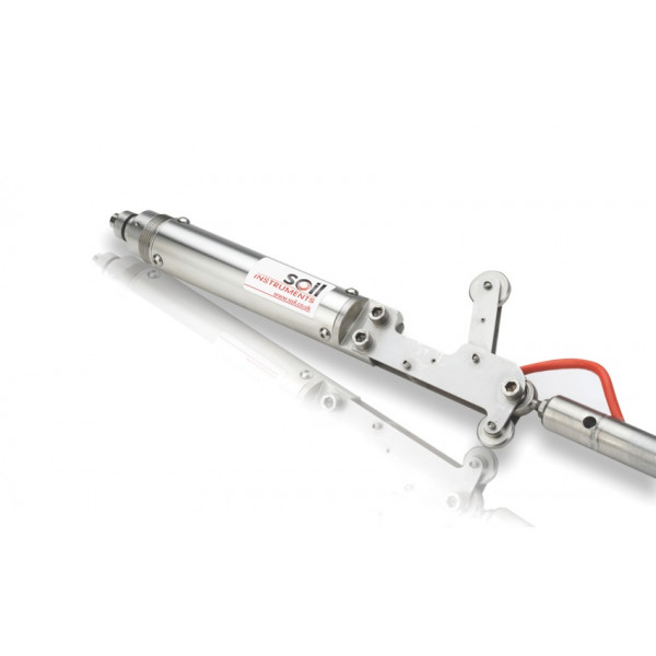
The Smart In-Place Inclinometer (Smart IPI) System is used to remotely monitor lateral displacement within a vertical borehole.
The Smart IPI System has been designed to supersede traditional IPI systems; with advanced technology and new mechanical design, the Smart IPI is seen as a new product rather than just an improvement to the old.
The Smart IPI System comprises in its most basic form a Data Acquisition system, a Sensor Interface Module, one Top Support Assembly, up to 39 Smart IPI Sensors and one Terminating Sensor.
The Easy-Connect Coupling and single cable approach lead to a much easier, quicker and more efficient installation as well as an increased number of sensors per borehole.